
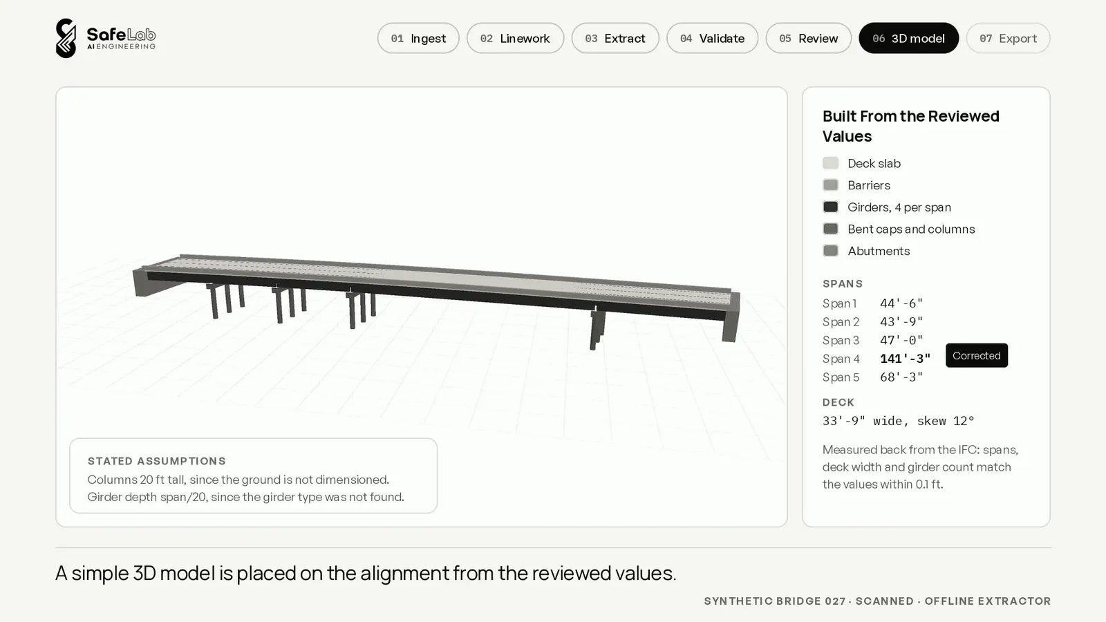
A bridge engineering firm asked us whether its as-built bridge plans, many of them scans of paper originals, could be turned into editable CAD and a 3D model. Within a week we had a working pipeline. It redraws each sheet as layered CAD, reads the engineering values, checks them against each other, and sends anything uncertain to an engineer.
The video below walks through one job from upload to export.
The Problem
For many older bridges, the as-built record exists only as a PDF. Some are vector exports from a CAD system. Many are scans of paper sheets: skewed, faded, and noisy. When a bridge needs rehabilitation, widening, or a model for asset management, someone has to redraft every line and retype every span, station, and elevation by hand before any design work starts.
The firm works in Bentley MicroStation and OpenRoads and in Autodesk tools. It wanted 2D CAD, a 3D model, or both, from the PDFs it already has.
What We Built
The pipeline runs in seven steps. Each step writes its results to the job folder, so any one of them can be rerun on its own.
- Ingest. Every page is rendered at 300 dpi, typed as vector, scanned, or mixed, and given a sheet role: general plan, elevation, typical section, or plan and profile. The scale is read from the title block. Scans go through OCR.
- Linework. Vector paths are sorted onto CAD layers by pen weight, dash pattern, and color. Scans are deskewed, cleaned, and traced into lines and arcs, then sorted by stroke width, arrowheads, dash runs, and hatch patterns. The result is a DXF per sheet with seven layers: heavy geometry, light geometry, dimensions, hidden lines, text, hatching, and border.
- Extract. The engineering values come off the sheets: span lengths, deck width, girder count and spacing, pier and abutment stations, elevations, and horizontal curve and vertical profile data. Every value carries its sheet, the box it was read from, a confidence score, and the exact text behind it.
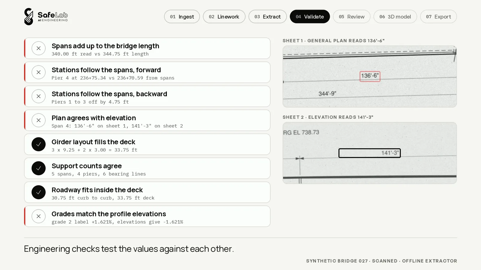
- Validate. The values are tested against each other with the same arithmetic an engineer would do: spans add up to the bridge length, stations follow the spans forward and backward, the girder layout fills the deck, curve length equals radius times the deflection angle, grades match the profile elevations, and the plan agrees with the elevation. When a check fails, it blames only the values nothing else confirms.
- Review. The engineer sees each flagged value next to a crop of its spot on the sheet. Saving a correction reruns the checks and rebuilds the model.
- 3D model. Deck, barriers, girders, bent caps, columns, and abutments are placed on the alignment and written as an IFC 4x3 model, with a glTF copy for the browser. The alignment and profile are written as LandXML. Where the sheets are silent, the model states its assumption on screen, for example column height when the ground is not dimensioned.
- Export. One zip holds the DXFs, the IFC, glTF, and LandXML files, every value as CSV and JSON, and a QA report with the checks, flags, and the engineer's edits.
One Job, Start to Finish
The demo runs a scanned five-span bridge from the synthetic test set. It comes back with flags. The span sum, the station checks in both directions, and the plan-to-elevation check all point at Span 4: the plan sheet reads 136'-6" and the elevation sheet reads 141'-3".
The engineer clicks the flag, the sheet zooms to the label, and they enter 141'-3". The checks rerun, the 3D model rebuilds on the corrected span, and the flag count drops from three to two. The two left over are the kind a person should decide: a grade labeled +1.621% that the profile elevations say is -1.621%, and a girder type with no callout anywhere on the sheets. Every edit is logged in the QA report.
How We Measured It
We built the test harness before the pipeline, because a tool that redraws engineering records has to be scored against known answers.
The synthetic set is 50 bridges with 2 to 5 spans of 40 to 150 feet, 4 to 8 girders, skews from 0 to 30 degrees, and tangent or curved alignments. Each bridge has four sheets, produced once as a clean vector PDF and once as a degraded scan (rotated, blurred, faded, noisy, and compressed). Ten bridges carry a deliberate inconsistency between sheets.
| Measure | Target | Vector PDFs | Scanned PDFs |
|---|---|---|---|
| Fields read correctly | 95% vector, 90% scanned | 99.5% (2,130 of 2,140) | 92.4% (1,977 of 2,140) |
| Wrong values left unflagged | Zero | 0 of 10 | 0 of 163 |
| Planted inconsistencies caught | All | 10 of 10 | 10 of 10 |
| Fields sent to the engineer | Under 20% | 1.5% | 16.2% |
| Median error on dimensioned lengths in the DXF | Under 0.5% | 0.00% | 0.02% |
| Spans, deck width, and girders in the IFC match the reviewed values | Within 0.1 ft | 50 of 50 | 44 of 44 built |
| Pipeline time per sheet, median | Report it | 0.1 seconds | 7.2 seconds |
The number that matters most is the second row. Of 173 values the pipeline got wrong, it flagged every one. On six scanned bridges a span or the girder layout could not be read, so the 3D model waits until the engineer fills that value in. The builder also refuses any span outside 10 to 400 feet, so a misread cannot turn into degenerate geometry.
Every output was also opened by software other than the library that wrote it. IfcOpenShell and web-ifc opened and meshed all 94 IFC models. Two independent DXF readers opened all 400 DXF files. The LandXML curve and profile data read back equal to the extracted values.
Real Sheets Are Harder
We also cut three public-record bridge plan sets from state DOT lettings into test cases: one scanned, one raster-only, and one vector. They hold 50 hand-labeled fields.
The offline parser read 12 of the 50 correctly. It flagged all 38 values it got wrong or could not find. The safety property held. Accuracy on real sheets is the open problem, because the offline parser was tuned to the synthetic drafting conventions, and real plan sets each follow their own. That gap is the job of the Claude extractor, which reads the full sheet, zoomed tiles, and the numbered OCR lines together, and has to tie every value it returns to the exact line it came from.
What Is Still Open
We told the firm exactly what the demo does not prove yet.
- The Claude extractor has not run live. Every number above comes from the offline rules parser. The Claude path is built and unit-tested.
- Hand checks in the firm's tools. Opening the outputs in MicroStation, AutoCAD, OpenRoads Designer, and Civil 3D needs licensed installs.
- A timed review. Someone who did not build the tool approves every flagged value on a job, timed, and that time is compared with redrafting the same sheets by hand.
- The firm's own sheets. They are held out of all tuning so the first run on them is a fair test.
The Rules We Kept
- The engineer verifies. The software drafts; a licensed engineer approves. Nothing is presented as automatic or stamped.
- No invented numbers. A value the sheets do not state is left empty with a reason. Where a value is derived from a relation the drawing prints, such as girder spacing from "N SPA @ ... = total", it is labeled as derived and sent to review.
- Client drawings stay private. Client sheets live outside version control and are sent nowhere except the model provider's API.
What to Take From This
If your firm has an archive of drawings that only exist as PDFs, the useful question is how you will know when the converted output is wrong. Score the tool against known answers before trusting it, tie every value to the spot it came from, test the values against each other, and keep the engineer in the loop for anything that disagrees.
That is how we approach custom AI systems, and it starts with an assessment of where the hours actually go. If you are deciding whether to build this kind of tool in-house, AI consultant vs. hiring an in-house AI engineer lays out the comparison.